Ems wrote:So, @OP, on topic
Between the lines I read that my comment is off topic. That is correct. My contribution belongs in the section "Tutorials, which nobody want to read". So I'll be brief.
Ems wrote:2. face normals are turned away from the camera. In other words, model is made of back-faces. No doubles like in the upper case, culling is unnecessary for this particular one, but face normals need to be flipped to front to be displayed correctly. I am aware of vertex normals and face normals, just btw.
This note contains parts that are true ... and parts that are false.
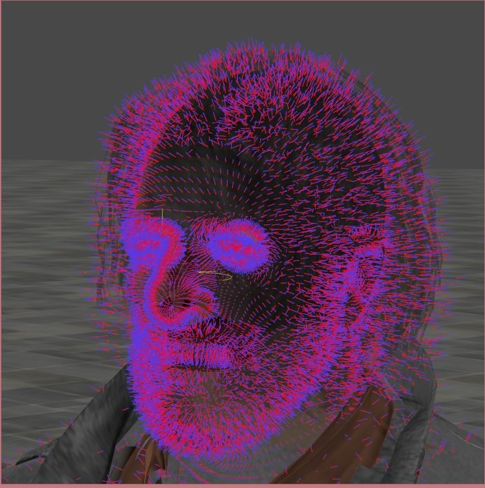
- False: The face normals are NOT turned away from the camera.
- False: face normals need NOT to be flipped
- True: The model is made of back-faces
btw, model formats holds ONLY vertex normals. A face normal is just the interpolation of the three vertex Normals of a triangle.
In computer graphics, back-face culling determines whether a polygon of a graphical object is visible. It is a step in the graphical pipeline on the video card, that tests whether the points in the polygon appear in clockwise or counter-clockwise order when projected onto the screen.
So the vertex order of the face determine if a face is a back face (face away from the
camera) or a front face.
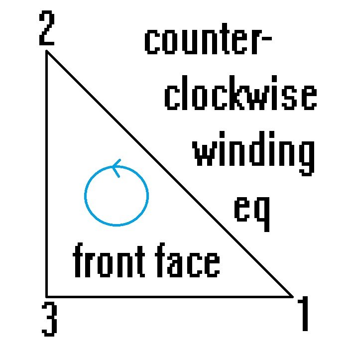
vs
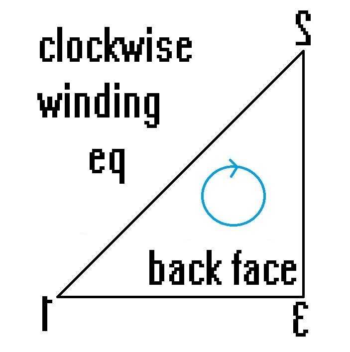
So:
- True: The vertex order must be changed
In XPS:
Ems wrote:1. mesh has duplicates, each set has front facing and back facing triangles. Culling renders them properly, by, well, literally culling back-faces that are not facing the camera, without it we get those "pretty" checkers, because everything is visible at once as I get it, and light is not rendered on the "back side", thus colour.
Some engines display polygons to have only one side, one is rendered opaque and the other is transparent. Putting doubles on those and flipping normals is a workaround that makes both sides visible from every angle.
This note contains parts that are true ... and parts that are false.
- True: light is NOT rendered CORRECT on the "back side"
- False: Everthing else
To make the shading, XNALara calculate the cosinus of the angle between the INVERTED Light direction eq shadow direction (b) and the direction of the Normal (a), using a dot product (|b| cos alpha)
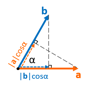
If the projection points to the same direction as the other vector, dot product is positive. If it has opposite direction, dot product is negative (XNALara clamp negative values to zero).
If now the shadow points to the opposite direction as the Normal vector the shading is bright. If light and Normal has the same direction the shading is dark.
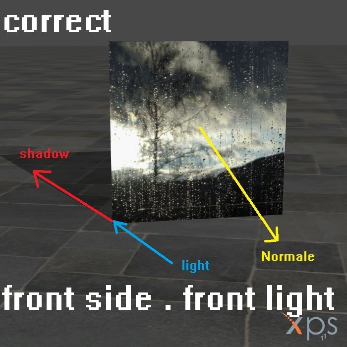

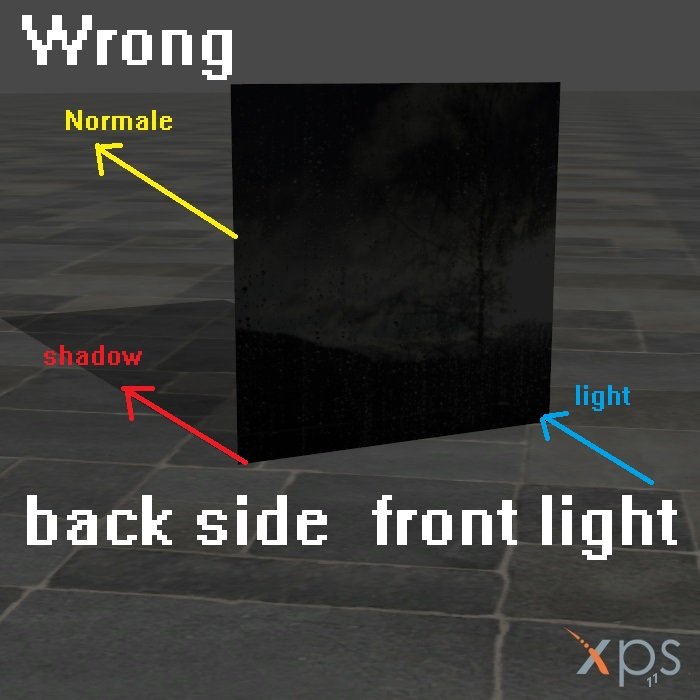
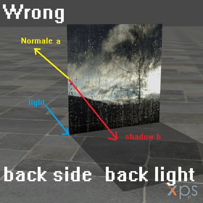
So all back sides (Normals points away from the camera) has a wrong shading. To bright for back lights and to dark for front lights,
since XNALara version 1.0 
But honestly, XNALara / XPS users are not interested in all this, as long as there know how to fix those issues visually

Culling do NOT renders them
properly. Culling do just
NOT RENDER the back faces, so it does not make any sense to add (or not remove) "back faces"

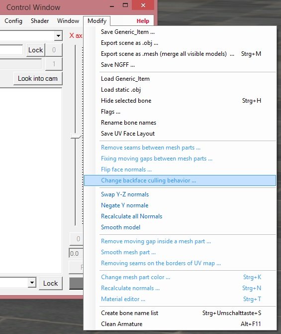
It is just NOT true that we don't have an option to control the use of culling, whether would that be via .xps or ngff.
We can choose between "counter clock wise" culling (Microsoft XNA framework default setting) and "clock wise" culling for every single mesh part of every single model ... and we can save it in every supported format (.xps, .mesh, .mesh.ascii, .obj and in NGFF):
We can choose between "counter clock wise" culling, "clock wise" culling and "no culling" via NGFF
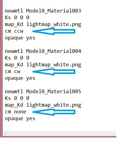
On this way, you can have a model with some meshes rendered with "back face culling" (cm ccw) and other meshes rendered without back face culling (cm none) ... and even some meshes rendered with "front face culling" (cm cw); or changing the winding without reorder the vertices.
It is just not true that "some engines display polygons to have only one side, one is rendered opaque and the other is transparent". Every game engine that i know (and I know as software developer a lot of engines) has a option to toggle BFC on or off. Even the simple XNA framework (game engine) can do it. Otherwise XPS would not have a option BFC/AC to make it. Even if there is such a engine (lets say Unity 4), it does not matter. Back face culling is done on your video card. The small program running on you video card is called "
shader". And every shader since
2001 allows to toggle backface culling on or off. It is a single line of code.
In HLSL it is "CullMode = CCW;" to toggle BFC to ON, and "CullMode = NONE;" to toggle BFC to OFF.
In OpenGL, BFC is disabled by default. It is "
glDisable" to toggle it OFF and "glEnable(GL_CULL_FACE);" to toggle it ON
It is false that "putting doubles on those and flipping normals is a workaround that makes both sides visible from every angle". "flipping normals" affect only the shading. You have also change the "
Winding order" (vertex order for the face).
Why should a model maker "putting doubles on those"? A simple attribute to render it "double sided" by apply an
two-sided shader to it; even "
double sided textured" with different UV-Sets (layer) on both sides it's enough.
I cannot believe that a professional modler will make a model with coincident faces without any needs to do it. A professional will allways
Avoiding Coincident Faces ... especially if the face is transparent. You know also, nobody want to order so much semi transparent faces
It is mostly a matter of a wrong tool to extract the game data. Just make a easy test. Create a sphere (in Blender) ... port it to XPS ... invoke a (Cel) outline shader ... grap it with "3D Ripper DX" ... examine the result in Blender: You have now 2 spheres. One with back faces (In other words, mesh is made of back-faces) surrounding the original sphere with front facing.
Ems wrote:Ok, now that's all I will bite on, because I don't have more energy to spare, and because I'd rather turn your attention to what is happening in 11.8.9, which I haven't noticed until now:
https://streamable.com/scc3nj
I dunno how to describe it. Normal maps are lightened incorrectly at the UV seams. Model matters not.
I cannot reproduce it. I need the model and the .scene file.
BTW: If you use google and search for "Normal maps are lightened incorrectly at the UV seams", you will get a lot of hits
Perhaps on the pipeline to port the model, you have used a tool which make the misstake and save the Normal map as "unsigned integer" .tga ? If so, you will allways get seams on the UV border.
Just comparing (127,127,255) versus (128,128,255) versus 0.0,0.0,1.0 ... because the middle of 0..255 is 127.5 ... and 127.5 cannot saved as integer value, you get a seam. None of this values are a "flat Normal map".
Anx had written a shader to "correct such wrong values" ... or more precice to try it.
https://www.deviantart.com/xnafreak/art ... -732363486 ... try it. (- Correct "Tangent Space Normal" mapping solved )
Read more:
https://community.khronos.org/t/normal- ... tion/74245
https://paroj.github.io/gltut/apas02.html
Most developer of such extract tools do not care about the difference between a image format and a texture. Google about "color of a flat Normal map", "normal map seams problem" or "Why normal map baking break at UV seams" to understand what I means.
A normal map is not as a colour map. A normal map is a texture holding 3D data (XYZ coords of the Normals), coded as fake colors.
Some porters do also use a 2D image editor to alter the Normalmaps. That cannot works too.
Lets say "Red 0" is "Normal points to left" eq "X = -1.0" and "Red 255" is "Normal points to right" eq "X = +1.0"
Lets say you you have a Normal map with 2 texel. One Normal points to left (RGB 0/0/0 eq XYZ -1.0/0.0/0.0) and the neighbor Normal points to right (RGB 255/0/0 eq XYZ 1.0/0.0/0.0)
Scale the Normal map by 1.5. So 2 pixel in the input texture are 3 pixel in the output.
With a 2D image editor, you get for the new pixel a "color interpolation". The result is:
RGB 0/0/0 127/0/0 255/0/0
or
RGB 0/0/0 128/0/0 255/0/0
(both false)
With a 3D Normal map tool, you get the right
texture values
XYZ -1.0/0.0/0.0 0.0/0.0/1.0 +1.0/0.0/0.0
saved as unsigned integer
image (.tga)
RGB 0/0/0 0/0/255 255/0/0


